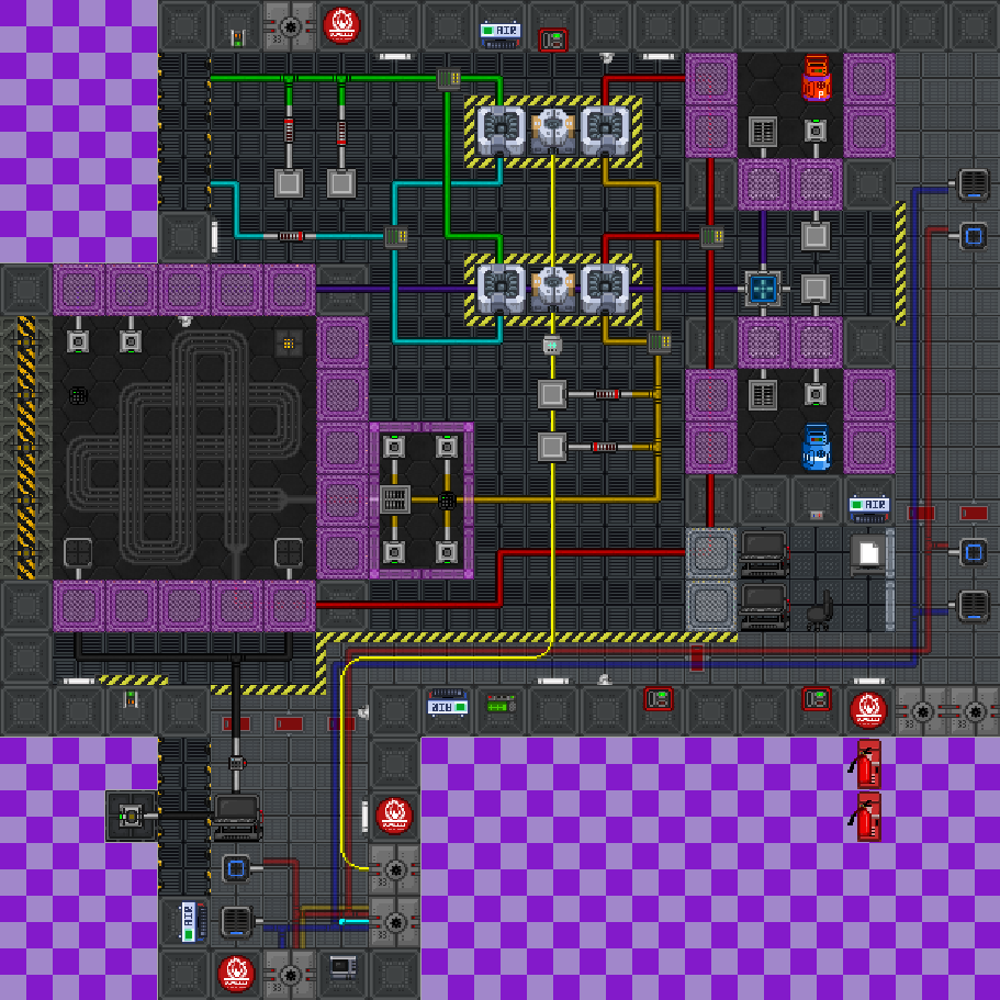
The Engine Room
The Engine room consists of:
- Engine chamber. The interior is 5x5, framed with heat resistant glass and reinforced walls.
- Two Gas Feed Chambers connected by an OmniMixer.
- A dual TEG setup, already hooked up to the loops.
- A Hot Loop overflow chamber.
- A monitoring area with two pump control consoles and the engine ignition button.
- A side area where a secondary emergency overflow vent is situated.
- A shutter control button for emergency venting of the entire chamber.
- Vacuum Radiator connections, where gases in the cold loop are cooled.
Engine Intent
As a TEG-based engine, the Burn Chamber relies on the heating and cooling of gas to spin turbines. Cold Loop gas is piped along a circuitous route - typically through space - to allow it to bleed off heat and grow colder. In contrast, Hot Loop gas is fed into the pipe loop inside the burn chamber. Although visually dramatic, the burning gas in the Chamber is not, in fact, what fills the hot loop. Instead, the continuous blaze in the chamber heats the gas contained within the Hot Loop through the insulated pipes.
Basic Set-Up
This is a baseline guide to make sure the shift doesn't go without power, and the engine doesn't explode. Any Engineer that knows their way around Engineering mechanics will tell you that this setup is suboptimal. It is important that the hazard steps are finished only after all previous steps are completed.
No Hazard:
- Put four cans of Phoron into the Cold Loop.
- Put two cans of Phoron into the Hot loop.
- Configure the OmniMixer to take Input from the North and South feeds, and Output to the West. You can experiment with different gas ratios to determine efficiency, but for a bare minimum set-up, 50:50 is acceptable.
- Using the consoles, turn on the vents in both gas chambers to begin feeding gas into the chamber line.
- Hazard step: Once the burn chamber is filled, press the ignition button to spark the reaction.
- Locate the gas pump along the cold pump line, max the flow, and activate the pump.
Engine set! Now, max the Input and Output on the Main SMES in the SMES room.
